Document Set · TRX-DS-012026-05Internal Engineering Only

Autonomous Follicular Restoration
Engineering Specification

High-fidelity reference for the integrated TRICHO-ROBOTIX platform: a 7-DOF surgical manipulator, 8K + ToF LiDAR perception stack, AI follicle classifier, and the companion bio-engineered hair follicle assembled from autologous bulge stem cells, dermal papilla spheroids, a graded PLGA/PCL micro-scaffold, and crosslinked hyaluronan ECM.

System cell — isometric configurationFIG 0.0 · SYSTEM OVERVIEW
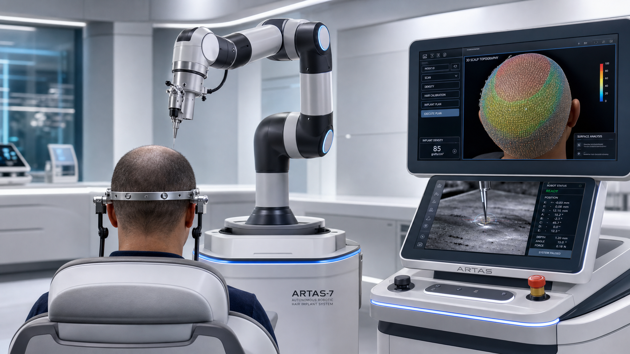
Rear view: 7-DOF robotic arm in raised ready-to-operate position behind the patient, poised above the occipital scalp
FIG · BLUEPRINT
DARK · 16:9

Key Performance Parameters

Aggregate system-level KPIs from RAS + BHF.

KPI-01
Cartesian repeatability
±0
µm
Implant depth tolerance
±0
µm
Target FU density
0
FU/cm²
Engraftment rate
0+
%
Procedure throughput
0
FU/hr
Image processing
0
ms/frame
Standards AlignmentSTD-01

The platform is engineered against the following normative documents. Pre-market conformance evidence is collated under the project DHF (Design History File).

  • IEC 60601-1General requirements for medical electrical equipment
  • IEC 60601-2-77Particular requirements for robotic surgical equipment
  • ISO 13482Robots and robotic devices — safety for personal-care robots
  • ISO 13485Quality management for medical devices
  • ISO 14971Risk management for medical devices
  • ISO 10993-1Biological evaluation of medical devices
  • ISO 11137Sterilization by gamma irradiation
  • ISO 17665Sterilization by moist heat
  • IEC 81001-5-1Cybersecurity for health-software life-cycle
Design PillarsPIL-01
  • Sub-50 µm precision
    Joint-level + actuator-level closed loops with hardware-validated repeatability.
  • PL d safety
    2oo3 sensor voting, dual-channel safety MCU, watchdog cascade.
  • Autologous biology
    Donor-derived eHFSCs + DP spheroids minimize MHC rejection risk.
  • Graded scaffold
    Apico-basal stiffness 1.8 → 0.18 MPa to match native niche.
RAS · SECTION ROOTSubsystems: 9

Autonomous Robotic Implantation System

Closed-loop surgical platform combining a 7-DOF manipulator, sub-50 µm force-feedback insertion control, 8K + ToF LiDAR perception, and an ISO 13482-aligned safety stack.

RAS · Mechanical, optical, and AI subsystemsFIG RAS.0
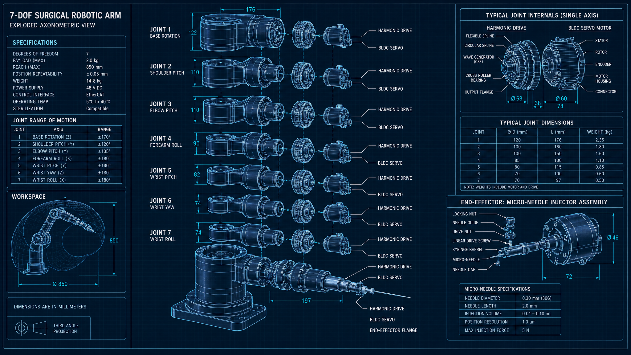
7-DOF robotic arm exploded view representing the robotic system
FIG · BLUEPRINT
DARK · 16:9
Subsystem IndexRAS-IDX
RAS-01 · REV B.2
7-DOF Surgical Manipulator

Redundant 7-DOF kinematic chain with harmonic-drive joints and high-resolution absolute encoders. Optimized for low-force, sub-50 µm repeatability inside a 600 mm spherical workspace.

RAS-02 · REV A.4
Force-Feedback Micro-Actuation

Distal voice-coil micro-actuator with integrated 6-axis F/T sensor provides closed-loop insertion depth control to ±50 µm and skin-tension monitoring at the needle interface.

RAS-03 · REV C.1
Cranial Fixation Ring & Ergonomic Frame

Ti-6Al-4V halo with viscoelastic polymer pads, fiducial markers, and articulated support frame. Maintains <0.2 mm registration drift for procedure duration.

RAS-04 · REV B.0
8K Optical & ToF LiDAR Module

33 MP global-shutter CMOS sensor co-registered with a ToF LiDAR array and polarized LED ring. Generates dense 4K depth maps of the scalp with <200 µm surface accuracy.

RAS-05 · REV D.1
AI Follicle Classification & Matrix Generation

Hybrid YOLOv8-seg + U-Net pipeline classifies follicular units (FU1–FU4), estimates exit angle (±5°), and emits the 3D implantation matrix on the scalp depth surface.

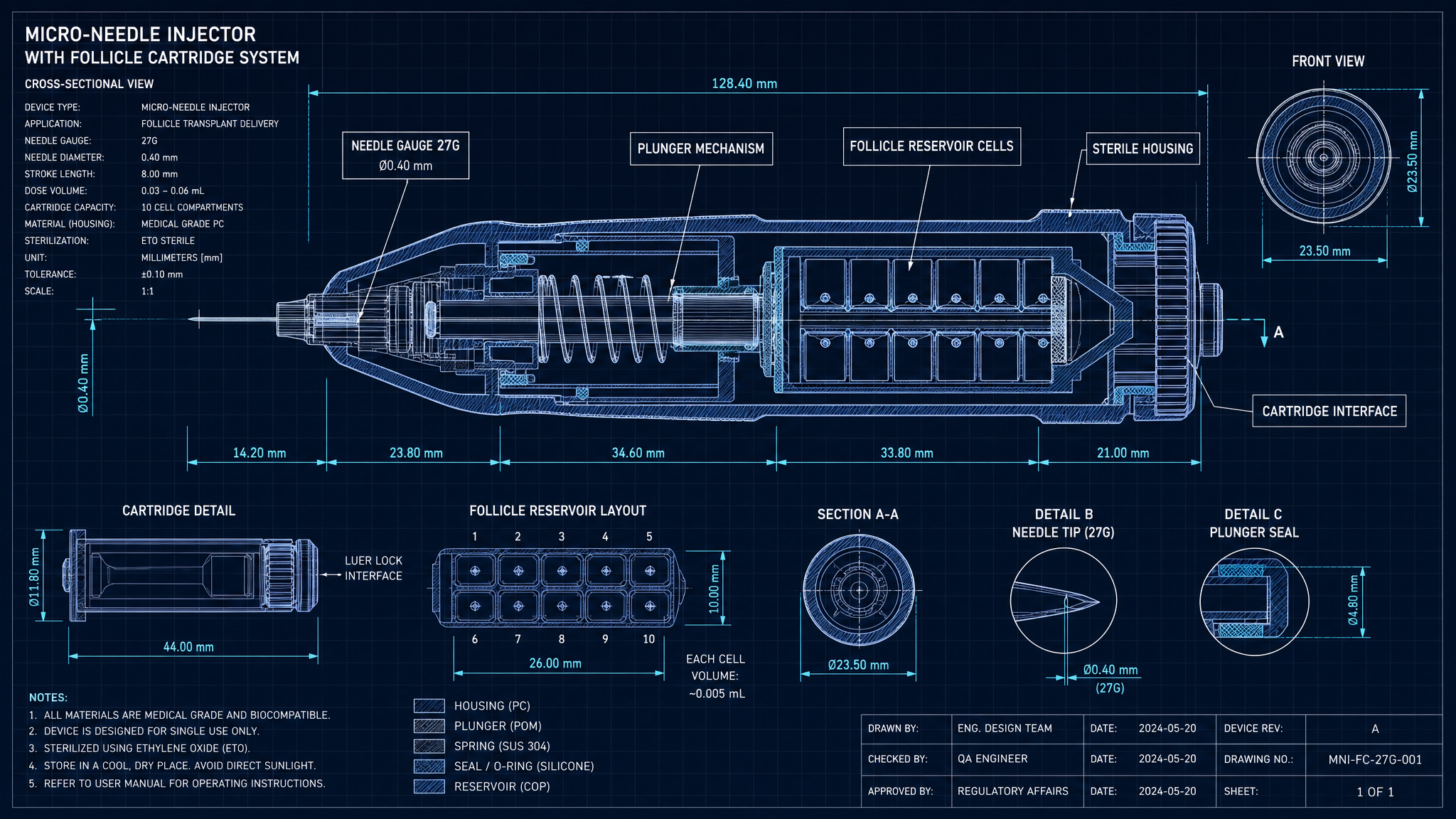
RAS-06 · REV B.3
Micro-Needle Injector & Follicle Cartridge

Single-use sterile cartridge with 27G thin-wall implanter needle, plunger-driven follicle release, and pre-loaded 200-cell follicle reservoir.

RAS-07 · REV A.6
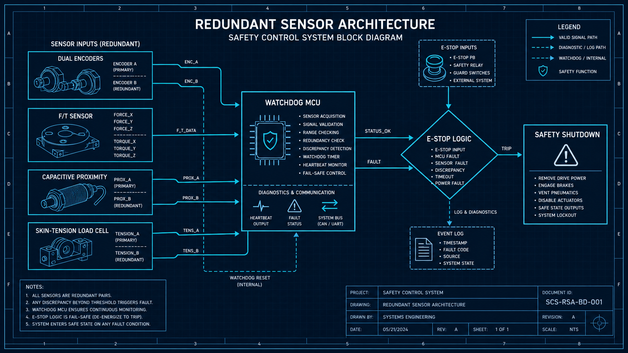
Safety, Redundancy & Standards Alignment

Triple-redundant sensor architecture, Category 3 PL d functional safety, ISO 13482 / IEC 60601-1 compliance, and watchdog-MCU brownout detection.

RAS-08 · REV A.2
Sterilization Workflow & Sterile Field

Mixed reprocessing strategy: autoclave for mechanical hardware, STERRAD VHP for sensor head, gamma for single-use cartridges. Validated SAL 10⁻⁶.

RAS-09 · REV A.0
Maintenance Access & Service Strategy

Tool-less access to joints 4–7, service-replaceable harmonic drive cartridges, MTBF target 20 000 h, and on-board self-diagnostic telemetry.

RAS-01REV B.2RAS

7-DOF Surgical Manipulator

Redundant 7-DOF kinematic chain with harmonic-drive joints and high-resolution absolute encoders. Optimized for low-force, sub-50 µm repeatability inside a 600 mm spherical workspace.

DOF
7
S-R-S redundant chain
Repeatability
±50 µm
ISO 9283, full load
Payload
3.0 kg
End-effector mass
Reach
600 mm
Sphere radius
Engineering DescriptionRAS-01 · DESC

The manipulator implements a kinematically redundant 7R serial topology (S-R-S layout) that maintains dexterity inside the constrained cranial workspace while allowing null-space self-motion for elbow positioning. Joints 1–4 carry the gross-positioning torque budget and use 100:1 harmonic-drive gear sets paired with frameless brushless DC servos. Joints 5–7, located distally, transition to lower-ratio (50:1) units to reduce inertia at the end-effector.

Each joint integrates a dual-encoder strategy — a 23-bit absolute optical encoder on the motor side for commutation and a 21-bit absolute encoder on the output side for closed-loop position. The output encoder is the truth source for the Cartesian controller; the residual difference between encoders is monitored continuously as a transmission-health signal.

Structural members are machined from aerospace-grade 7075-T6 aluminum with surface-passivated, anodized finish (Type II, Class 2). Interfaces in contact with the sterile field are overmolded with autoclave-tolerant PEEK shrouds (Tg ≈ 143 °C) that allow STERRAD VHP cycles.

Technical ParametersRAS-01 · TABLE
ParameterValueUnitTolerance / Note
Degrees of freedom7Redundant S-R-S
Cartesian repeatability±50µmISO 9283-3
Joint pos. resolution21bit abs.Output side
Motor encoder23bit abs.Motor side
Max joint velocity120°/sJoints 1–4
Max TCP velocity500mm/sSoftware-limited to 80 mm/s in procedure mode
Payload at TCP3.0kg
Workspace radius600mmSpherical
Harmonic drive ratio100:1 / 50:1J1–4 / J5–7
Servo typeFrameless BLDCSlot-less for low cogging
Control loop rate4kHzEtherCAT DC-sync
Structural alloy7075-T6 AlHard-anodized Type II Class 2
IP ratingIP54Procedure side
Redundancy resolutionNOTE-1

Null-space projection uses a weighted Jacobian pseudo-inverse with manipulability gradient ∇w(q); singular-value floor enforced at 5e-3 to prevent rank collapse near vertical TCP poses.

Thermal managementNOTE-2

Joints 1–3 use forced-convection rear plates with 40 mm low-noise fans; joints 4–7 are passively cooled through anodized aluminum heat-spreaders. Continuous duty derated to 85 % at 40 °C ambient.
RAS-02REV A.4RAS

Force-Feedback Micro-Actuation

Distal voice-coil micro-actuator with integrated 6-axis F/T sensor provides closed-loop insertion depth control to ±50 µm and skin-tension monitoring at the needle interface.

Depth tolerance
±50 µm
Closed-loop
Force resolution
5 mN
Z-axis
BW
350 Hz
Closed-loop
Stroke
15 mm
Needle reciprocation
Engineering DescriptionRAS-02 · DESC

The end-effector houses a voice-coil linear actuator (VCA) optimized for low-mass reciprocation of the needle holder. The moving carriage (8.4 g) rides on cross-roller guides with sub-micron straightness, driven by a current-mode amplifier at 8 kHz update rate. A 6-axis silicon strain-gauge F/T sensor sits between the actuator base and the needle cartridge interface, providing simultaneous force and torque feedback.

Insertion depth is controlled in a cascaded loop: an outer position loop (1 kHz) commands a force-saturated inner velocity loop, with a feed-forward Z-impedance term derived from a Kelvin–Voigt scalp tissue model (k ≈ 1.8 N/mm, c ≈ 0.04 N·s/mm). When the scalp-tension load cell crosses 0.6 N preload threshold, the controller transitions from velocity to force-tracking mode for the final 1.2 mm of stroke.

Closed-loop insertion force profilePLOT · RAS-02
Loading chart…

Modeled Fz vs. depth; first cyan band marks skin pierce, second marks graft release transition.

Technical ParametersRAS-02 · TABLE
ParameterValueUnitTolerance / Note
Actuator typeVoice-coil (VCA)Custom Lorentz coil
Carriage mass8.4g
Stroke length15mm
Peak force6.0N
Continuous force2.4N
Position resolution0.5µmLinear optical scale
F/T sensor axes6Fx, Fy, Fz, Tx, Ty, Tz
Force resolution (Fz)5mN
F/T sample rate8kHz
Insertion depth tolerance±50µm
Closed-loop bandwidth350Hz
Skin-tension threshold0.6NTriggers force-mode handoff
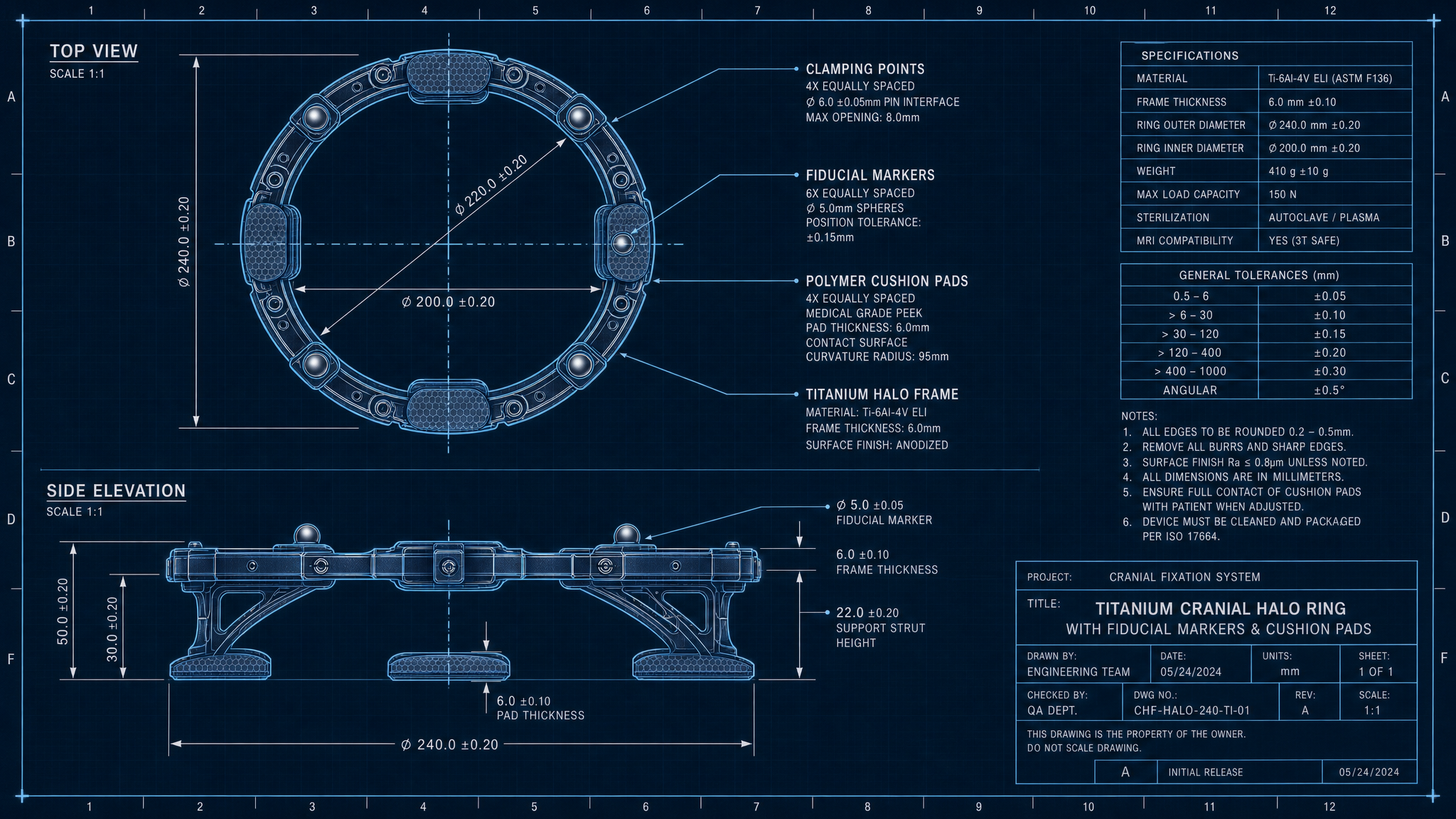
RAS-03REV C.1RAS

Cranial Fixation Ring & Ergonomic Frame

Ti-6Al-4V halo with viscoelastic polymer pads, fiducial markers, and articulated support frame. Maintains <0.2 mm registration drift for procedure duration.

Cranial Fixation Ring & Ergonomic FrameFIG RAS-03
Top and side blueprint view of titanium cranial fixation halo
FIG · BLUEPRINT
DARK · 16:9
Engineering DescriptionRAS-03 · DESC

The fixation halo is a single-piece Ti-6Al-4V (ELI grade 23) ring with six contact stations spaced at 60° intervals. Each station carries a viscoelastic polyurethane cushion (Shore 30A, durometer-stable through autoclave) that compresses 2–3 mm under nominal clamping force. The system reaches kinematic seating against the cranial vault without exceeding 4.5 N/cm² of contact pressure, which is well below the published capillary occlusion threshold for scalp tissue.

Three retro-reflective fiducial spheres (Ø 9.5 mm, sub-100 µm sphericity) are embedded in the halo at known geometric offsets. These provide the camera+LiDAR module a rigid optical reference for registering the patient frame to the robot base frame. Registration RMS error after Procrustes alignment is held below 120 µm.

The ergonomic frame is a 3-segment articulated arm with locking ball joints (M6 collet) that anchors the halo to the procedure chair. After clinician-driven coarse positioning, all joints are torqued to 8.5 N·m — verified by an integrated strain-gauge sleeve — producing rated drift below 0.2 mm over a 4-hour procedure window.

Technical ParametersRAS-03 · TABLE
ParameterValueUnitTolerance / Note
Halo materialTi-6Al-4V ELI (Grade 23)ASTM F136
Halo mass380g
Contact stations660° spacing
Pad materialPolyurethane Shore 30A
Max contact pressure4.5N/cm²
Fiducial diameter9.5mm
Fiducial sphericity<100µm
Registration RMS error<120µm
Drift over 4 h<0.20mm
Frame torque8.5N·mAll articulating joints
SterilizationAutoclave 134 °C / 18 minHalo + frame
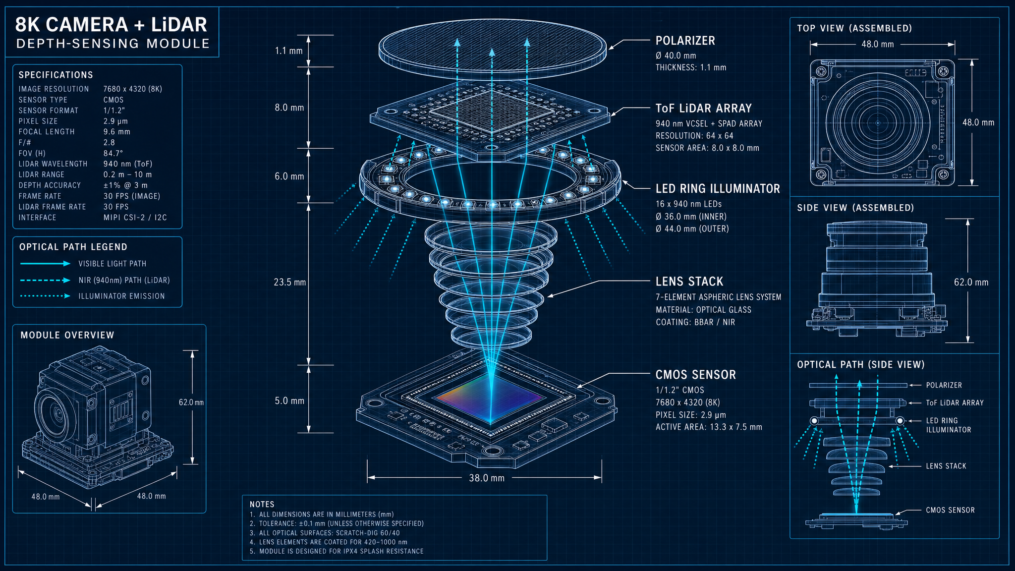
RAS-04REV B.0RAS

8K Optical & ToF LiDAR Module

33 MP global-shutter CMOS sensor co-registered with a ToF LiDAR array and polarized LED ring. Generates dense 4K depth maps of the scalp with <200 µm surface accuracy.

8K Optical & ToF LiDAR ModuleFIG RAS-04
8K camera and LiDAR depth-sensing module exploded schematic
FIG · BLUEPRINT
DARK · 16:9
Engineering DescriptionRAS-04 · DESC

The optical head couples a Sony IMX661-class 33 MP global-shutter monochrome sensor (3.45 µm pixel pitch) with a 5-element F/2.4 fixed-focus lens stack designed for 250 mm nominal working distance. A toroidal LED ring (940 nm + visible bands) provides cross-polarized illumination that suppresses specular skin reflection and improves follicle contrast by 7–9 dB.

A 64×64-element indirect ToF LiDAR array is rigidly co-mounted with the camera and externally calibrated to the camera frame within 30 µm / 0.05° (5×5×5 grid Tsai-Lenz calibration). The fused output is a dense 4K depth map at 30 Hz with surface accuracy held under 200 µm over the working volume.

Calibration is verified pre-procedure via a checkerboard plus 3-sphere artifact; the system rejects calibration if reprojection error exceeds 0.25 px or if any axis depth bias exceeds 150 µm.

Technical ParametersRAS-04 · TABLE
ParameterValueUnitTolerance / Note
SensorIMX661-class CMOSGlobal shutter, mono
Resolution8192 × 432033.2 MP
Pixel pitch3.45µm
Max frame rate60fpsFull-frame, 10-bit
LensF/2.4, fixed 250 mm WD
IlluminationCross-polarized LED ring940 nm + 450/520/630 nm
LiDAR modalityIndirect ToF64 × 64 array
Depth map output4K @ 30Hz
Surface accuracy<200µm
Cross-calibration30 µm / 0.05°Tsai-Lenz
Reprojection limit0.25pxCal-reject threshold
RAS-05REV D.1RAS

AI Follicle Classification & Matrix Generation

Hybrid YOLOv8-seg + U-Net pipeline classifies follicular units (FU1–FU4), estimates exit angle (±5°), and emits the 3D implantation matrix on the scalp depth surface.

AI Follicle Classification & Matrix GenerationFIG RAS-05
AI-generated implantation matrix and timeline diagram
FIG · BLUEPRINT
DARK · 16:9
Engineering DescriptionRAS-05 · DESC

A YOLOv8-seg backbone, trained on ≈ 1.4 M annotated scalp tiles across Fitzpatrick I–VI, produces per-follicle bounding masks at 60 ms inference (TensorRT FP16, RTX A4500). Each detection is routed through a lightweight 3-stage classifier head that assigns one of {FU1, FU2, FU3, FU4} based on shaft count and mutual spacing.

Exit angle and direction are estimated by a separate U-Net regression head that consumes the cross-polarized + IR channels and the local depth patch. Mean absolute angular error on the validation set is 4.7° (σ = 2.1°). Direction vectors are converted from camera frame to scalp-surface tangent frame using local LiDAR normals.

The 3D implantation matrix is built by Poisson-disk sampling on the scalp surface under hard constraints: minimum inter-implant spacing 0.8 mm, target density 25–40 FU/cm², and angular distribution matched to the native follicle field via von Mises–Fisher KDE.

Technical ParametersRAS-05 · TABLE
ParameterValueUnitTolerance / Note
Detection backboneYOLOv8-segCustom 5-class head
Classification head3-stage MLPFU1/FU2/FU3/FU4 + reject
Training corpus~1.4 M tilesFitzpatrick I–VI
Inference latency60msTensorRT FP16
[email protected] (detection)0.93Hold-out test set
FU classification F10.91
Angle MAE4.7°
Min inter-implant spacing0.8mm
Target density25–40FU/cm²
SamplerPoisson-disk + vMF KDE
Active-learning loopNOTE-1

Procedure-time disagreements between the YOLO head and the operator override are silently logged (PHI-stripped) and queued into the weekly retraining batch.

RAS-06REV B.3RAS

Micro-Needle Injector & Follicle Cartridge

Single-use sterile cartridge with 27G thin-wall implanter needle, plunger-driven follicle release, and pre-loaded 200-cell follicle reservoir.

Micro-Needle Injector & Follicle CartridgeFIG RAS-06
Cross-section of the micro-needle injector cartridge
FIG · BLUEPRINT
DARK · 16:9
Engineering DescriptionRAS-06 · DESC

The implanter needle is a 27G (OD 0.413 mm, ID 0.21 mm) thin-wall stainless steel hypodermic with a 12° back-bevel and electropolished tip (Ra < 0.2 µm). The needle is press-fit into a polycarbonate hub that mates to the voice-coil actuator with a kinematic 3-ball coupling repeatable to ±10 µm.

The cartridge is a single-use Class IIa device: a 200-cell follicle reservoir with individually addressed micro-wells (Ø 0.9 mm × 4 mm deep) on a rotary indexer driven by a stepper motor through a magnetic feedthrough so the sterile barrier is unbroken. Each well is pre-filled with 3.5 µL of preservation medium (Hypothermosol-FRS).

Cartridges are pre-sterilized by gamma irradiation at 25–40 kGy and shipped in a Tyvek peel pouch; the secondary tray is RFID-tagged with lot, expiry, and dosimetry confirmation that the control system verifies before unlock.

Technical ParametersRAS-06 · TABLE
ParameterValueUnitTolerance / Note
Needle gauge27 GThin-wall
Needle OD0.413mm
Needle ID0.21mm
Bevel angle12°Back-bevel
Tip Ra<0.2µmElectropolished
Reservoir cells200Rotary indexer
Well dimensionsØ0.9 × 4mm
Preservation mediumHypothermosol-FRS3.5 µL / well
Coupling repeatability±10µmKinematic 3-ball
SterilizationGamma 25–40 kGyPer ISO 11137
Shelf life18monthsRFID-verified expiry
ClassIIaEU MDR
RAS-07REV A.6RAS

Safety, Redundancy & Standards Alignment

Triple-redundant sensor architecture, Category 3 PL d functional safety, ISO 13482 / IEC 60601-1 compliance, and watchdog-MCU brownout detection.

Safety, Redundancy & Standards AlignmentFIG RAS-07
Safety system schematic block diagram
FIG · BLUEPRINT
DARK · 16:9
Engineering DescriptionRAS-07 · DESC

Safety functions are partitioned across a dedicated dual-channel safety MCU running a SIL-2-rated micro-kernel. The primary E-stop circuit (Category 1 stop, IEC 60204-1) is wired in series across both safety relays; loss of either channel forces the manipulator brakes engaged within 25 ms.

The collision-avoidance layer fuses (a) per-joint motor current observers — a 2σ deviation triggers a Cartesian stop, (b) a capacitive proximity skin around joints 5–7 with detection range 5–20 mm, and (c) the F/T sensor with 0.4 N collision threshold. All three are wired into the safety MCU’s 2oo3 voting logic.

The system targets Performance Level d (PL d) per ISO 13849-1 with hardware fault tolerance HFT = 1. It is being qualified to IEC 60601-1 third edition (general medical electrical equipment) plus the 60601-2-77 collateral for robotic surgical equipment.

Technical ParametersRAS-07 · TABLE
ParameterValueUnitTolerance / Note
Functional safety targetPL dISO 13849-1
Hardware fault tolerance1HFT
Safety MCUDual-channel lockstepSIL-2 micro-kernel
E-stop category1IEC 60204-1
Brake engage time<25ms
Collision threshold (F/T)0.4N
Capacitive prox. range5–20mm
Encoder redundancy2× abs. per joint
StandardsIEC 60601-1, 60601-2-77, ISO 13482, ISO 14971
Cyber-securityIEC 81001-5-1Premarket
Watchdog cascadeNOTE-1

Three independent watchdogs: motion controller (1 ms), safety MCU (200 µs), and supervisor PC (50 ms). A single watchdog timeout demotes the system to a configurable safe-state; two within 100 ms forces a hard E-stop.

RAS-08REV A.2RAS

Sterilization Workflow & Sterile Field

Mixed reprocessing strategy: autoclave for mechanical hardware, STERRAD VHP for sensor head, gamma for single-use cartridges. Validated SAL 10⁻⁶.

Engineering DescriptionRAS-08 · DESC

Reprocessing partitions the system into three sterility classes. Mechanical hardware (halo, frame, distal shroud, needle holder) is steam-autoclaved at 134 °C for 18 min per ISO 17665. The sensor head and electronics shroud are VHP-compatible (STERRAD 100NX standard cycle) since steam is incompatible with the lens cement and CMOS package.

Single-use cartridges are gamma-irradiated at 25–40 kGy per ISO 11137 with verified SAL of 10⁻⁶. Each lot is dosimetry-mapped and the dose-mapping report is linked to the cartridge RFID payload so the robot rejects out-of-spec lots.

The sterile field is established with a draped, sealed end-effector shroud that mates to the kinematic coupling through a sterile silicone bellows; bellows leakage is monitored by a 0.5 kPa differential-pressure sensor.

Technical ParametersRAS-08 · TABLE
ParameterValueUnitTolerance / Note
Autoclave cycle134 °C / 18 minISO 17665, halo + frame + shroud
VHP cycleSTERRAD 100NX stdSensor head + electronics shroud
Gamma dose25–40kGyCartridges only
Validated SAL10⁻⁶Per ISO 11137 / 17665
Bellows leak threshold0.5kPa
Reprocessing cycles≥ 200Mechanical hardware lifecycle
RAS-09REV A.0RAS

Maintenance Access & Service Strategy

Tool-less access to joints 4–7, service-replaceable harmonic drive cartridges, MTBF target 20 000 h, and on-board self-diagnostic telemetry.

Engineering DescriptionRAS-09 · DESC

Joints 4–7 are designed as line-replaceable units (LRUs) with a quick-release V-band clamp that frees the joint module from the link in under 90 s. Harmonic drive cartridges are pre-greased, sealed, and field-swappable at 10 000 h or upon flex-spline backlash exceeding 0.05°.

A continuous-monitoring service-data bus exports 142 telemetry channels (per-joint current, temperature, vibration RMS, encoder residual, fan tachometer) into a Prometheus endpoint sampled at 2 Hz. Engineering can pull rolling 30-day windows for trend analysis.

Annual preventive maintenance includes lens recalibration (Tsai-Lenz target), F/T sensor zero-drift check, brake torque test (≥ 14 N·m per joint), and full ISO 9283 repeatability re-qualification.

Technical ParametersRAS-09 · TABLE
ParameterValueUnitTolerance / Note
Joint LRU swap time<90s
Harmonic drive service interval10 000h
Flex-spline backlash limit0.05°
Telemetry channels142Prometheus, 2 Hz
MTBF target20 000h
Annual PM duration4h
Brake torque (min)14N·m
BHF · SECTION ROOTSubsystems: 8

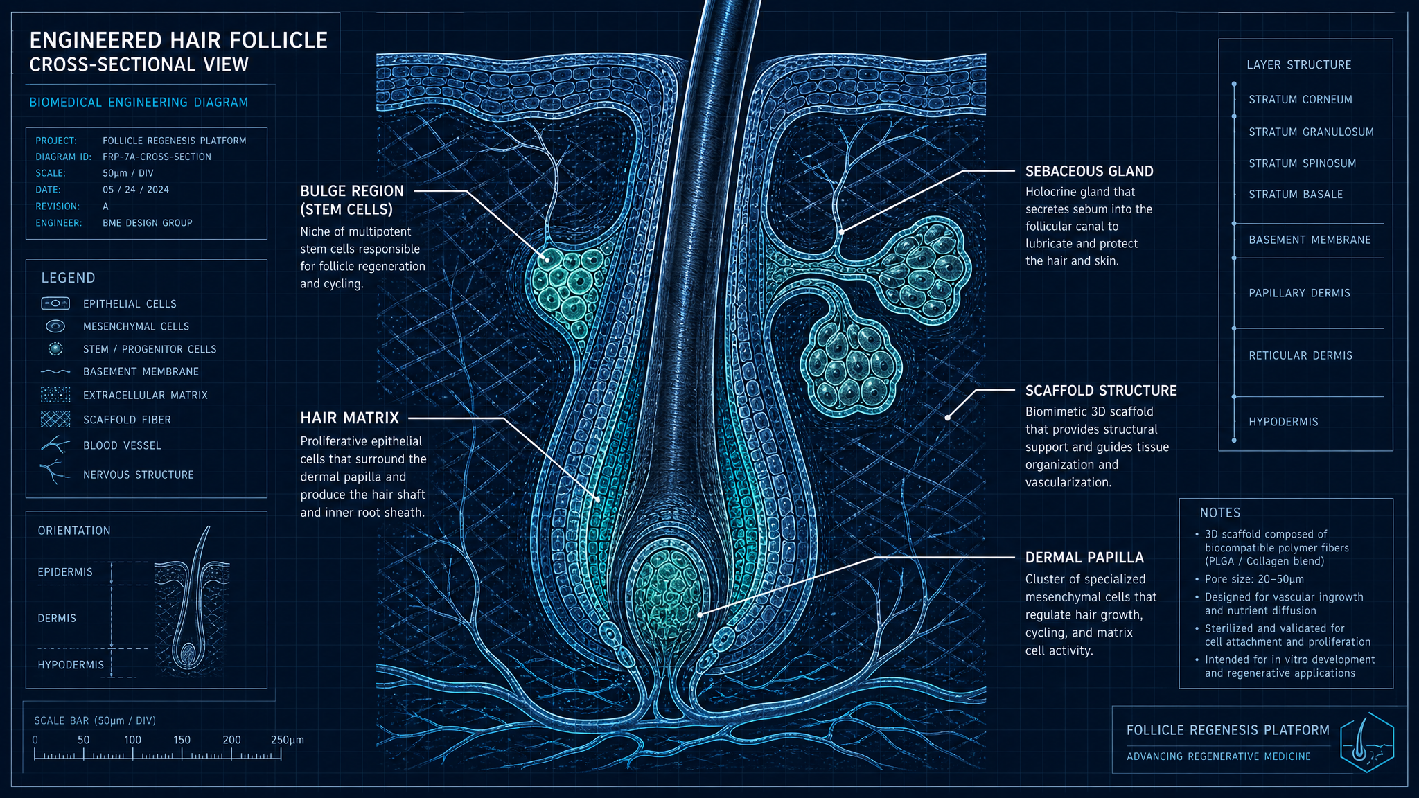
Bio-Engineered Hair Follicle

Autologous, co-cultured engineered follicle on a gradient-stiffness PLGA/PCL micro-scaffold embedded in crosslinked hyaluronan hydrogel with VEGF/PDGF-loaded sustained-release microspheres.

BHF · Cellular biology, scaffold design & integrationFIG BHF.0
Cross-section of the engineered hair follicle showing scaffold and cellular layers
FIG · BLUEPRINT
DARK · 16:9
Subsystem IndexBHF-IDX
BHF-01 · REV C.0
Bulge Epithelial Stem Cells

CD200⁺ / K15⁺ / K19⁺ epithelial stem cells isolated by FACS from autologous occipital donor follicles, expanded under defined KSFM conditions.

BHF-02 · REV C.2
Dermal Papilla Cells & Inductive Signaling

Dermal papilla cells expanded as 3D spheroids to preserve inductive signature (ALP⁺, versican⁺, corin⁺) and rescue hair-inductive capacity lost in 2D.

BHF-03 · REV B.4
Epithelial–Mesenchymal Co-culture

Layered co-culture aggregates eHFSCs with DP spheroids in a defined cocktail (CHIR99021, LDN-193189, FGF7) that recapitulates the Wnt↑/BMP↓/FGF↗ induction window.

BHF-04 · REV B.1
Crosslinked Hyaluronan Hydrogel ECM

Thiol-ene crosslinked methacrylated hyaluronic acid hydrogel with storage modulus G′ ≈ 1.2 kPa, controlled enzymatic degradation, and tunable RGD presentation.

BHF-05 · REV D.0
PLGA/PCL Micro-scaffold with Gradient Stiffness

3D-melt-printed PLGA 75:25 / PCL biphasic micro-scaffold with 50–150 µm interconnected pores and an apico-basal stiffness gradient mirroring the native follicular niche.

BHF-06 · REV B.0
Angiogenic & Immunomodulatory Cargo

PLGA microspheres encapsulating VEGF-165, PDGF-BB, TGF-β3 and IL-10 with engineered burst + sustained release over 21 days.

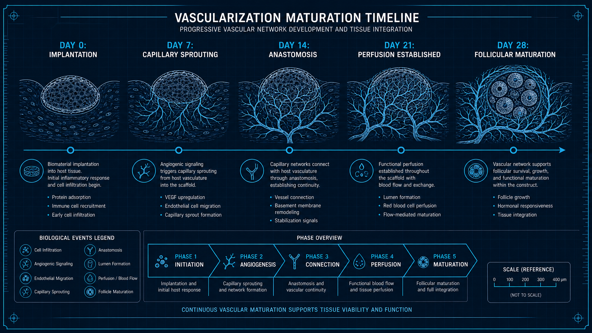
BHF-07 · REV B.3
Implantation, Vascularization & Maturation Timeline

Day 0–28 integration: implant → capillary sprouting (D3–7) → anastomosis (D10–14) → perfusion (D14–21) → follicular maturation and shaft eruption (D28+).

BHF-08 · REV A.5
Immune Compatibility & Biocompatibility

Autologous cellular fraction (low rejection risk) combined with ISO 10993 biocompatibility-qualified materials and an IL-10/TGF-β3 tolerogenic micro-niche.

BHF-01REV C.0BHF

Bulge Epithelial Stem Cells

CD200⁺ / K15⁺ / K19⁺ epithelial stem cells isolated by FACS from autologous occipital donor follicles, expanded under defined KSFM conditions.

Engineering DescriptionBHF-01 · DESC

Bulge epithelial stem cells (eHFSCs) are harvested from autologous occipital scalp punches (2 mm) under local anesthesia. After enzymatic dissociation (collagenase IV, 2 mg/mL, 90 min), single-cell suspensions are FACS-sorted on a CD200⁺ / CD34⁻ / integrin α6ʰⁱ / K15⁺ profile. Yield is 1.2–2.0 × 10⁴ eHFSCs per follicular unit.

Cells are expanded on lethally-irradiated 3T3-J2 feeder layers in defined KSFM (keratinocyte serum-free medium) supplemented with EGF (5 ng/mL), bFGF (10 ng/mL), and Rho-kinase inhibitor Y-27632 (10 µM) for the first 48 h to suppress apoptotic signaling at low density. We hold passages ≤ P4 to limit clonogenic potential drift; population doublings tracked in real time.

Technical ParametersBHF-01 · TABLE
ParameterValueUnitTolerance / Note
SourceAutologous occipital2 mm punch
Sort markersCD200⁺ / K15⁺ / K19⁺ / α6ʰⁱFACS
Yield1.2–2.0 × 10⁴cells/FU
Expansion mediumKSFM + EGF/bFGF/Y-27632
Feeder layerIrradiated 3T3-J2±60 Gy
Passage limit≤ P4
Doubling time24–30h
Clonogenicity≥ 12% holoclonesP4
BHF-02REV C.2BHF

Dermal Papilla Cells & Inductive Signaling

Dermal papilla cells expanded as 3D spheroids to preserve inductive signature (ALP⁺, versican⁺, corin⁺) and rescue hair-inductive capacity lost in 2D.

Engineering DescriptionBHF-02 · DESC

Dermal papilla (DP) cells are microdissected from donor follicles, dispase-released, and seeded on low-attachment U-bottom plates at 3000 cells/well to form spheroids (Ø ≈ 180 µm by 72 h). Spheroid culture mitigates the well-documented loss of inductivity that DP cells suffer in monolayer past P2 — the spheroid state restores >70 % of the native ALP⁺ / versican⁺ / corin⁺ signature.

Inductivity is functionally validated by a co-graft assay: DP spheroids + neonatal keratinocytes implanted into NSG-mouse silicone chambers must produce ≥ 8 pigmented hair shafts per chamber at day 21 before clinical use.

Technical ParametersBHF-02 · TABLE
ParameterValueUnitTolerance / Note
SourceAutologous donor follicles
Spheroid size180µm3000 cells/well, 72 h
Inductive markersALP, versican, corin, α-SMA
Inductivity restoration≥ 70% native signature
Co-graft validation≥ 8 shafts / chamberNSG mouse, day 21
Passage limit≤ P3 (2D) / P6 (spheroid)
BHF-03REV B.4BHF

Epithelial–Mesenchymal Co-culture

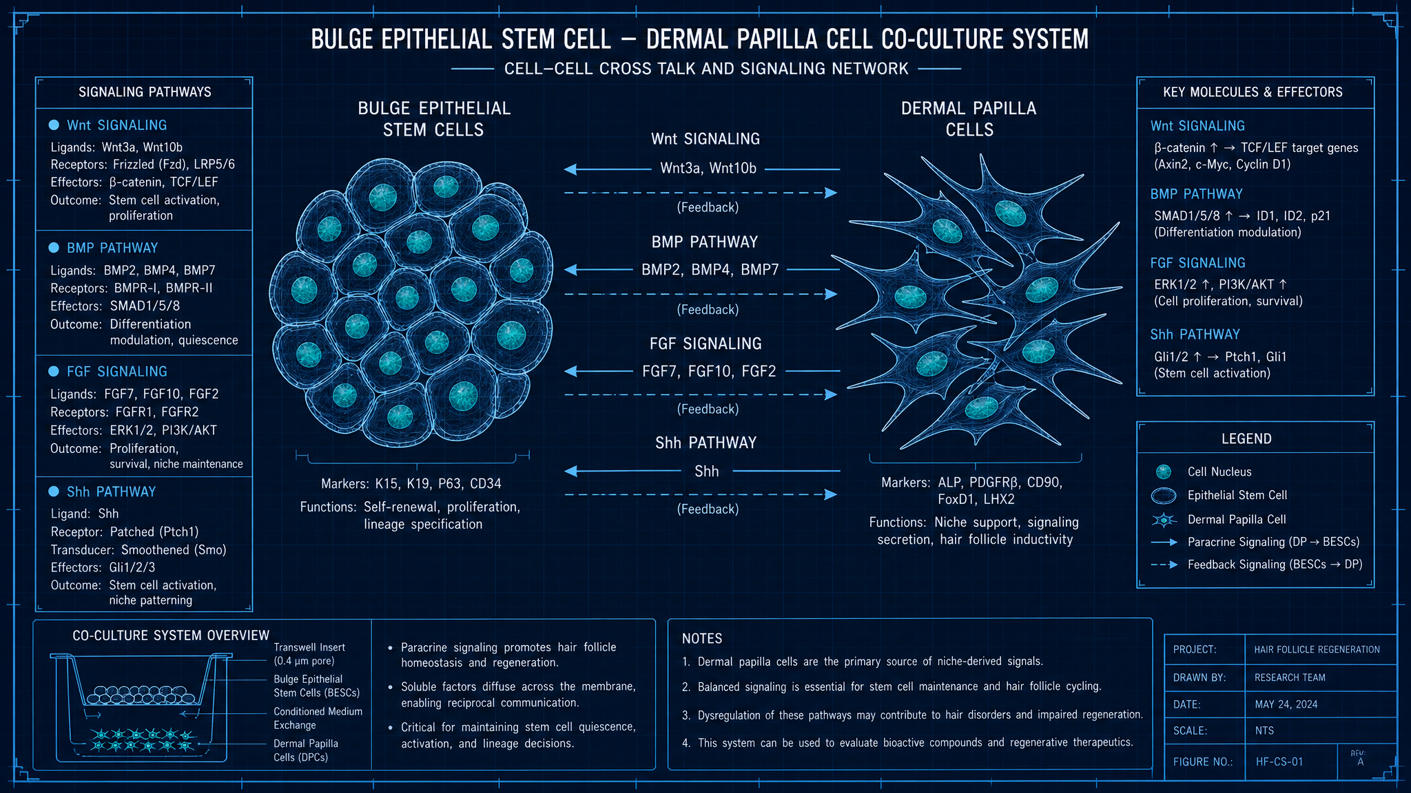
Layered co-culture aggregates eHFSCs with DP spheroids in a defined cocktail (CHIR99021, LDN-193189, FGF7) that recapitulates the Wnt↑/BMP↓/FGF↗ induction window.

Epithelial–Mesenchymal Co-cultureFIG BHF-03
Stem cell and dermal papilla co-culture signaling diagram
FIG · BLUEPRINT
DARK · 16:9
Engineering DescriptionBHF-03 · DESC

Co-culture aggregates are assembled by depositing 8–10×10³ eHFSCs onto a single DP spheroid in a U-well, producing a layered organoid in which epithelial cells crawl over and partially encapsulate the mesenchymal core. The aggregate is then transferred into a custom defined medium that mimics the induction signaling window.

Pathway tuning: Wnt is activated via CHIR99021 (3 µM, GSK3β inhibitor); BMP is suppressed with LDN-193189 (100 nM, ALK2/3 inhibitor); FGF7 (10 ng/mL) and Shh agonist SAG (50 nM) drive early follicle germ specification. Cocktail is applied 0–6 days, then withdrawn for FGF-driven elongation.

Aggregate quality control: at day 7 we require ≥ 60 % LEF1⁺ / SOX9⁺ co-expression in the epithelial compartment as a positive marker of follicular induction.

Pathway modulation (induction vs maintenance)PLOT · BHF-03
Loading chart…

Normalized pathway activity bias between D0–6 induction window and D7+ maintenance phase.

Technical ParametersBHF-03 · TABLE
ParameterValueUnitTolerance / Note
Aggregate composition8–10k eHFSCs + 1 DP spheroid
Wnt activatorCHIR99021 3 µM
BMP inhibitorLDN-193189 100 nM
FGFFGF7 10 ng/mL
Shh agonistSAG 50 nM
Cocktail window0–6days
Day-7 QC threshold≥ 60 % LEF1⁺/SOX9⁺
BHF-04REV B.1BHF

Crosslinked Hyaluronan Hydrogel ECM

Thiol-ene crosslinked methacrylated hyaluronic acid hydrogel with storage modulus G′ ≈ 1.2 kPa, controlled enzymatic degradation, and tunable RGD presentation.

Engineering DescriptionBHF-04 · DESC

The primary extracellular matrix mimic is a methacrylated hyaluronic acid (MeHA) hydrogel crosslinked through visible-light thiol-ene chemistry with a 4-arm PEG-dithiol (lithium phenyl-2,4,6-trimethylbenzoylphosphinate photoinitiator, 405 nm, 5 mW/cm², 60 s). This avoids the cytotoxicity of UV/Irgacure 2959 systems while preserving cell viability >95 % at encapsulation.

Bulk mechanical tuning targets G′ of 1.2 kPa (soft dermal tissue) and a loss tangent below 0.10 at 1 Hz. RGD adhesion peptide is conjugated at 1.5 mM via thiol-Michael addition for integrin engagement. Hyaluronidase-mediated degradation half-life is held at ≈ 14 days in vitro to coincide with the scaffold ingrowth window.

Technical ParametersBHF-04 · TABLE
ParameterValueUnitTolerance / Note
Base polymerMethacrylated HAMethacrylation DS ≈ 25 %
Crosslinker4-arm PEG-dithiol
PhotoinitiatorLAP 0.05 % w/v
Cure405 nm / 5 mW/cm² / 60 s
Storage modulus G′1.2kPa1 Hz, 37 °C
Loss tangent (tan δ)<0.101 Hz
RGD density1.5mM
Degradation t½~14daysHyaluronidase mediated
Cell viability post-cure>95%
BHF-05REV D.0BHF

PLGA/PCL Micro-scaffold with Gradient Stiffness

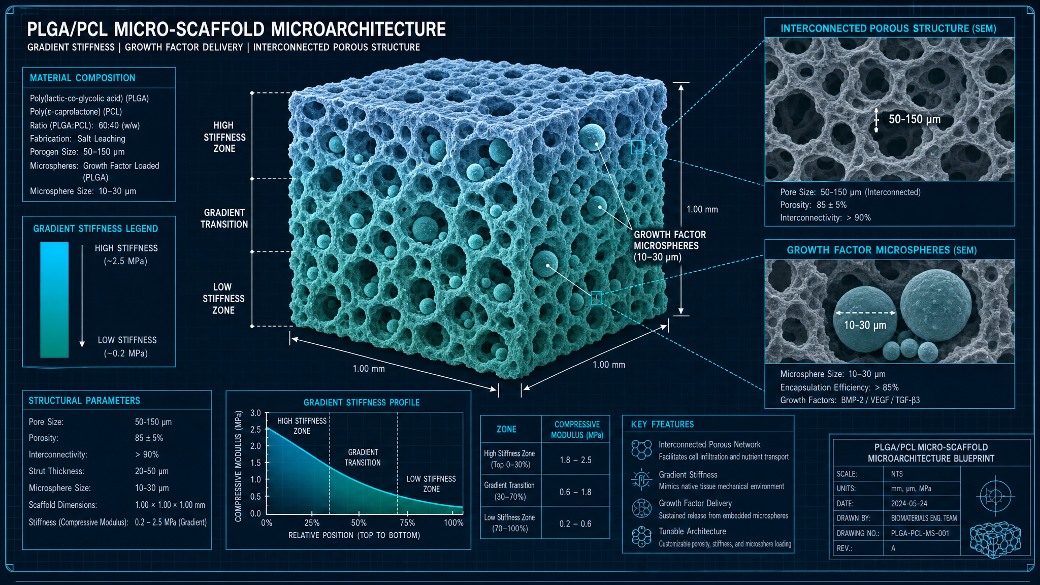
3D-melt-printed PLGA 75:25 / PCL biphasic micro-scaffold with 50–150 µm interconnected pores and an apico-basal stiffness gradient mirroring the native follicular niche.

PLGA/PCL Micro-scaffold with Gradient StiffnessFIG BHF-05
SEM-style PLGA/PCL scaffold micro-architecture
FIG · BLUEPRINT
DARK · 16:9
Engineering DescriptionBHF-05 · DESC

The structural backbone of the engineered follicle is a melt-electrowritten (MEW) PLGA(75:25)/PCL biphasic micro-scaffold, fabricated as a cylindrical lattice 0.9 mm OD × 4 mm. The MEW process holds fiber diameter at 18 ± 3 µm and produces interconnected porosity in the 50–150 µm range, validated by micro-CT (Bruker SkyScan 1272, 2 µm voxel).

A graded stiffness profile is achieved by progressively decreasing the PCL fraction along the apico-basal axis (upper bulge region 25 % PCL → lower bulb region 5 % PCL). This produces a measured compressive modulus gradient from 1.8 MPa apically to 0.18 MPa basally, mimicking the natural mechano-environment between rigid outer root sheath and compliant papilla.

Encapsulated PLGA microspheres (Ø 12 µm) carrying VEGF-165, PDGF-BB, and TGF-β3 are embedded in the basal third of the scaffold during the post-print solvent-annealing step. Degradation in vivo proceeds biphasically: PLGA mass loss 50 % at ≈ 6 weeks, PCL skeleton persisting beyond 12 weeks to provide mechanical support during follicular maturation.

Apico-basal stiffness gradientPLOT · BHF-05
Loading chart…

Compressive modulus profile measured by nano-indentation along the long axis of the scaffold.

Technical ParametersBHF-05 · TABLE
ParameterValueUnitTolerance / Note
Polymer systemPLGA 75:25 + PCLGradient ratio
FabricationMelt-electrowriting (MEW)In-house 8-axis MEW
Scaffold dim.Ø0.9 × 4mm
Fiber diameter18 ± 3µm
Pore size50–150µmµCT-validated
Apical modulus1.8MPaCompressive
Basal modulus0.18MPa
PLGA t½ in vivo~6weeks
PCL persistence>12weeks
Endotoxin<0.5EU/deviceLAL test
BHF-06REV B.0BHF

Angiogenic & Immunomodulatory Cargo

PLGA microspheres encapsulating VEGF-165, PDGF-BB, TGF-β3 and IL-10 with engineered burst + sustained release over 21 days.

Engineering DescriptionBHF-06 · DESC

Growth factors and immunomodulatory cytokines are loaded into double-emulsion PLGA (50:50) microspheres (Ø 12 ± 2 µm, span <0.7) with bovine serum albumin as a stabilizing co-encapsulant. Loading efficiencies are 78–85 % for VEGF-165, 81 % for PDGF-BB, 72 % for TGF-β3, and 84 % for IL-10.

Release follows a designed burst-then-sustained profile: 22 % cumulative release at 24 h (initial burst), reaching 85 % at day 21. Daily release rates are calibrated to maintain local VEGF in the 50–100 ng/mL range during the angiogenic window (day 3–10).

IL-10 and TGF-β3 establish a tolerogenic local milieu that biases tissue-resident macrophages toward an M2 (CD163⁺ / CD206⁺) phenotype during the first 10 days, suppressing foreign-body fibrotic encapsulation around the scaffold.

Cumulative release kinetics (in vitro)PLOT · BHF-06
Loading chart…

Designed burst (≈22 % @ 24 h) followed by sustained release through day 28.

Technical ParametersBHF-06 · TABLE
ParameterValueUnitTolerance / Note
Microsphere polymerPLGA 50:50
Microsphere diameter12 ± 2µm
VEGF-165 loading eff.78–85%
PDGF-BB loading eff.81%
TGF-β3 loading eff.72%
IL-10 loading eff.84%
24 h burst22%
Cumulative day 2185%
Local VEGF target50–100ng/mLDay 3–10
Macrophage polarization>65 % M2Day 10
BHF-07REV B.3BHF

Implantation, Vascularization & Maturation Timeline

Day 0–28 integration: implant → capillary sprouting (D3–7) → anastomosis (D10–14) → perfusion (D14–21) → follicular maturation and shaft eruption (D28+).

Engineering DescriptionBHF-07 · DESC

Implantation proceeds with the robot positioning the cartridge needle along the AI-generated 3D matrix and the voice-coil actuator driving needle penetration to a depth controlled by the surface depth-map plus a fixed 1.4 mm offset into the reticular dermis. The follicle–scaffold construct is then ejected by the plunger and released as the needle retracts.

Days 0–2 are dominated by hemostasis and platelet release of PDGF. From day 3 through day 7, endothelial sprouts driven by the VEGF gradient migrate from peri-implant capillary plexus into the basal microsphere zone of the scaffold. Anastomosis with host vasculature is observed by day 10–14 (perfusion confirmed by laser-Doppler).

By day 21 the engineered follicle is fully perfused and the LEF1⁺ hair germ progresses through the elongation phase. First pigmented hair shaft emergence is observed on day 24–28 in pre-clinical large-animal studies (n = 12, mean = 26.4 d, σ = 1.8 d).

Vascularization stages (D0→D28)PLOT · BHF-07
Loading chart…

Local perfusion fraction measured by laser-Doppler imaging at each integration stage.

Technical ParametersBHF-07 · TABLE
ParameterValueUnitTolerance / Note
Implant depth1.4mmBelow surface, reticular dermis
Capillary sproutingD3–7
AnastomosisD10–14
Full perfusionD14–21
First shaft emergence26.4 ± 1.8dn = 12 large-animal
Engraftment rate≥ 92%Day 28
BHF-08REV A.5BHF

Immune Compatibility & Biocompatibility

Autologous cellular fraction (low rejection risk) combined with ISO 10993 biocompatibility-qualified materials and an IL-10/TGF-β3 tolerogenic micro-niche.

Engineering DescriptionBHF-08 · DESC

Because the cellular fraction is fully autologous (donor-derived eHFSCs and DP cells) the construct is not subject to MHC-driven rejection. The risk surface therefore reduces to foreign-body response (FBR) against the synthetic scaffold and any residual contaminants.

All synthetic materials — MeHA, PLGA, PCL, PEG-dithiol, microsphere shell — are individually qualified to the ISO 10993 series: –10993-5 (cytotoxicity, MEM elution), –10993-6 (implantation 12 weeks rat subcutaneous), –10993-10 (irritation/sensitization, GLP guinea-pig maximization), –10993-11 (systemic toxicity), and –10993-23 (chemical characterization). The composite device is then run through full -10993-1 BER (biological evaluation report).

Locally, IL-10 and TGF-β3 release from the scaffold biases macrophages toward an M2 phenotype during the critical first 10 days. Endotoxin per device is held below 0.5 EU (LAL), pyrogenicity tested by monocyte activation test (MAT) per Ph. Eur. 2.6.30.

Technical ParametersBHF-08 · TABLE
ParameterValueUnitTolerance / Note
Rejection riskMinimalAutologous cellular fraction
Biocomp. standardISO 10993-1+ subordinate -5/-6/-10/-11/-23
Endotoxin limit<0.5EU/device
PyrogenicityMAT (Ph. Eur. 2.6.30)
M2 macrophage ratio>65%Day 10 local infiltrate
Capsule thickness<80µmDay 28 histology
SPEC-IDX-01Cross-system

Combined Specification Index

Flattened view of every published parameter, tolerance, and reference value across the RAS and BHF subsystems. Single source of truth for downstream design reviews and requirement-trace matrices.

Autonomous Robotic Implantation SystemRAS · 9 subsystems
ParameterValueUnitNote
Degrees of freedom7Redundant S-R-S
Cartesian repeatability±50µmISO 9283-3
Joint pos. resolution21bit abs.Output side
Motor encoder23bit abs.Motor side
Max joint velocity120°/sJoints 1–4
Max TCP velocity500mm/sSoftware-limited to 80 mm/s in procedure mode
Payload at TCP3.0kg
Workspace radius600mmSpherical
Harmonic drive ratio100:1 / 50:1J1–4 / J5–7
Servo typeFrameless BLDCSlot-less for low cogging
Control loop rate4kHzEtherCAT DC-sync
Structural alloy7075-T6 AlHard-anodized Type II Class 2
IP ratingIP54Procedure side
ParameterValueUnitNote
Actuator typeVoice-coil (VCA)Custom Lorentz coil
Carriage mass8.4g
Stroke length15mm
Peak force6.0N
Continuous force2.4N
Position resolution0.5µmLinear optical scale
F/T sensor axes6Fx, Fy, Fz, Tx, Ty, Tz
Force resolution (Fz)5mN
F/T sample rate8kHz
Insertion depth tolerance±50µm
Closed-loop bandwidth350Hz
Skin-tension threshold0.6NTriggers force-mode handoff
ParameterValueUnitNote
Halo materialTi-6Al-4V ELI (Grade 23)ASTM F136
Halo mass380g
Contact stations660° spacing
Pad materialPolyurethane Shore 30A
Max contact pressure4.5N/cm²
Fiducial diameter9.5mm
Fiducial sphericity<100µm
Registration RMS error<120µm
Drift over 4 h<0.20mm
Frame torque8.5N·mAll articulating joints
SterilizationAutoclave 134 °C / 18 minHalo + frame
ParameterValueUnitNote
SensorIMX661-class CMOSGlobal shutter, mono
Resolution8192 × 432033.2 MP
Pixel pitch3.45µm
Max frame rate60fpsFull-frame, 10-bit
LensF/2.4, fixed 250 mm WD
IlluminationCross-polarized LED ring940 nm + 450/520/630 nm
LiDAR modalityIndirect ToF64 × 64 array
Depth map output4K @ 30Hz
Surface accuracy<200µm
Cross-calibration30 µm / 0.05°Tsai-Lenz
Reprojection limit0.25pxCal-reject threshold
ParameterValueUnitNote
Detection backboneYOLOv8-segCustom 5-class head
Classification head3-stage MLPFU1/FU2/FU3/FU4 + reject
Training corpus~1.4 M tilesFitzpatrick I–VI
Inference latency60msTensorRT FP16
[email protected] (detection)0.93Hold-out test set
FU classification F10.91
Angle MAE4.7°
Min inter-implant spacing0.8mm
Target density25–40FU/cm²
SamplerPoisson-disk + vMF KDE
ParameterValueUnitNote
Needle gauge27 GThin-wall
Needle OD0.413mm
Needle ID0.21mm
Bevel angle12°Back-bevel
Tip Ra<0.2µmElectropolished
Reservoir cells200Rotary indexer
Well dimensionsØ0.9 × 4mm
Preservation mediumHypothermosol-FRS3.5 µL / well
Coupling repeatability±10µmKinematic 3-ball
SterilizationGamma 25–40 kGyPer ISO 11137
Shelf life18monthsRFID-verified expiry
ClassIIaEU MDR
ParameterValueUnitNote
Functional safety targetPL dISO 13849-1
Hardware fault tolerance1HFT
Safety MCUDual-channel lockstepSIL-2 micro-kernel
E-stop category1IEC 60204-1
Brake engage time<25ms
Collision threshold (F/T)0.4N
Capacitive prox. range5–20mm
Encoder redundancy2× abs. per joint
StandardsIEC 60601-1, 60601-2-77, ISO 13482, ISO 14971
Cyber-securityIEC 81001-5-1Premarket
ParameterValueUnitNote
Autoclave cycle134 °C / 18 minISO 17665, halo + frame + shroud
VHP cycleSTERRAD 100NX stdSensor head + electronics shroud
Gamma dose25–40kGyCartridges only
Validated SAL10⁻⁶Per ISO 11137 / 17665
Bellows leak threshold0.5kPa
Reprocessing cycles≥ 200Mechanical hardware lifecycle
ParameterValueUnitNote
Joint LRU swap time<90s
Harmonic drive service interval10 000h
Flex-spline backlash limit0.05°
Telemetry channels142Prometheus, 2 Hz
MTBF target20 000h
Annual PM duration4h
Brake torque (min)14N·m
Bio-Engineered Hair FollicleBHF · 8 subsystems
ParameterValueUnitNote
SourceAutologous occipital2 mm punch
Sort markersCD200⁺ / K15⁺ / K19⁺ / α6ʰⁱFACS
Yield1.2–2.0 × 10⁴cells/FU
Expansion mediumKSFM + EGF/bFGF/Y-27632
Feeder layerIrradiated 3T3-J2±60 Gy
Passage limit≤ P4
Doubling time24–30h
Clonogenicity≥ 12% holoclonesP4
ParameterValueUnitNote
SourceAutologous donor follicles
Spheroid size180µm3000 cells/well, 72 h
Inductive markersALP, versican, corin, α-SMA
Inductivity restoration≥ 70% native signature
Co-graft validation≥ 8 shafts / chamberNSG mouse, day 21
Passage limit≤ P3 (2D) / P6 (spheroid)
ParameterValueUnitNote
Aggregate composition8–10k eHFSCs + 1 DP spheroid
Wnt activatorCHIR99021 3 µM
BMP inhibitorLDN-193189 100 nM
FGFFGF7 10 ng/mL
Shh agonistSAG 50 nM
Cocktail window0–6days
Day-7 QC threshold≥ 60 % LEF1⁺/SOX9⁺
ParameterValueUnitNote
Base polymerMethacrylated HAMethacrylation DS ≈ 25 %
Crosslinker4-arm PEG-dithiol
PhotoinitiatorLAP 0.05 % w/v
Cure405 nm / 5 mW/cm² / 60 s
Storage modulus G′1.2kPa1 Hz, 37 °C
Loss tangent (tan δ)<0.101 Hz
RGD density1.5mM
Degradation t½~14daysHyaluronidase mediated
Cell viability post-cure>95%
ParameterValueUnitNote
Polymer systemPLGA 75:25 + PCLGradient ratio
FabricationMelt-electrowriting (MEW)In-house 8-axis MEW
Scaffold dim.Ø0.9 × 4mm
Fiber diameter18 ± 3µm
Pore size50–150µmµCT-validated
Apical modulus1.8MPaCompressive
Basal modulus0.18MPa
PLGA t½ in vivo~6weeks
PCL persistence>12weeks
Endotoxin<0.5EU/deviceLAL test
ParameterValueUnitNote
Microsphere polymerPLGA 50:50
Microsphere diameter12 ± 2µm
VEGF-165 loading eff.78–85%
PDGF-BB loading eff.81%
TGF-β3 loading eff.72%
IL-10 loading eff.84%
24 h burst22%
Cumulative day 2185%
Local VEGF target50–100ng/mLDay 3–10
Macrophage polarization>65 % M2Day 10
ParameterValueUnitNote
Implant depth1.4mmBelow surface, reticular dermis
Capillary sproutingD3–7
AnastomosisD10–14
Full perfusionD14–21
First shaft emergence26.4 ± 1.8dn = 12 large-animal
Engraftment rate≥ 92%Day 28
ParameterValueUnitNote
Rejection riskMinimalAutologous cellular fraction
Biocomp. standardISO 10993-1+ subordinate -5/-6/-10/-11/-23
Endotoxin limit<0.5EU/device
PyrogenicityMAT (Ph. Eur. 2.6.30)
M2 macrophage ratio>65%Day 10 local infiltrate
Capsule thickness<80µmDay 28 histology